
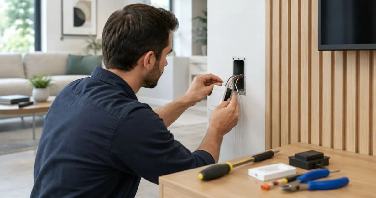
Instead of repeatedly removing trim to fix a buried switch, plan wiring smart switches behind wall panels around an accessible electrical box, a supported switch, and the finished wall depth. Complete and test the electrical work before fitting decorative panels, then keep the switch and its connections accessible through the removable faceplate.
- Wiring smart switches behind wall panels requires accessible electrical boxes, not connections hidden behind decorative cladding.
- The Panel Hub wall panels suit homeowners updating decorative walls; electrical compatibility depends on the switch and installation.
- Confirm neutral requirements, load compatibility, and finished wall depth before cutting panels.
- Have an electrician handle wiring changes, box extensions, and unfamiliar multi-location circuits.
Why this matters
A decorative wall changes the surface around a switch. It does not turn the space behind the panels into an approved electrical enclosure. Keep every wiring connection inside an appropriate box, and keep that box accessible without damaging the wall finish.
The Panel Hub is best for homeowners choosing decorative wall panels, not for determining smart-switch electrical compatibility. When planning your The Panel Hub installation, treat the panel layout and electrical layout as separate decisions that must meet at the same finished surface.
For a 2026 renovation, the key question is not whether a switch looks flush. It is whether the box, mounting arrangement, wiring, and connected light meet the device instructions and locally adopted electrical requirements.
Before you start
- Gather the actual specifications. Have the smart-switch installation manual, light or driver specifications, panel thickness, backing details, and proposed faceplate. Arrange a qualified electrician for wiring changes and confirm local permit requirements.
- Confirm access and connectivity. You need access to the circuit breaker and, for connected functions, the manufacturer's required app, account, hub, or wireless network. Identify whether the light operates from one location or multiple locations.
- Check the hidden depth problem first. Added panels and battens move the finished wall forward. A faceplate can conceal a recessed box without making it compliant; select the box-extension arrangement before cutting the panel opening.
Do not begin by disconnecting wires to discover what they do. If the existing circuit is unfamiliar, have an electrician identify it before purchasing the replacement switch or committing to the panel layout.
Circuit and switch compatibility
This first configuration unit decides whether your chosen switch belongs on the existing circuit. Smart switches are not interchangeable simply because their faceplates look alike.
- Identify the circuit arrangement. Establish whether the existing control is single-location, multi-location, or part of a dimming system. Have an electrician identify supply, switched conductors, grounding, and any shared-circuit conditions.
- Check the neutral requirement. Read the exact switch manual. Some devices require a neutral at the switch box; others use a different approved arrangement. A white conductor alone does not establish that a usable neutral is present.
- Match the connected load. Confirm that the device supports the light, LED driver, or other equipment it will control. A lighting switch is not automatically suitable for a fan motor, and a dimmer requires compatible dimmable equipment.
- Check voltage and enclosure space. A common US household lighting circuit is 120 volts, but the electrician must confirm the actual supply and device rating. Confirm that the box has adequate capacity for the conductors, connectors, grounding, and replacement device.
- Confirm the connected features. If the device specifies 2.4 GHz Wi-Fi, check that your network supports that band at the switch location. For a hub-based device, verify the required hub and its compatibility before installation.
Expected result: You have a supported switch, an identified circuit, and a connection plan taken from the device's own instructions—not a generic wire-color diagram.
For your 2026 project, retain the exact model instructions with your renovation records. Similar-looking switches can have different neutral, companion-device, and load requirements.
Finished wall and electrical box
The finished surface includes everything added over the existing wall: panels, backing, battens, and any mounting layer. Measure that complete assembly rather than relying on the decorative panel thickness alone.
- Measure the build-out. Record the distance from the existing wall surface to the proposed finished face. Dry-fit a sample near the switch without opening or disturbing its wiring.
- Locate the box opening. Mark the opening independently of the panel pattern. Keep access to the device mounting screws and enough clearance to remove the switch for future service.
- Resolve the box position. Have the electrician choose a listed extension, replacement box, or other approved arrangement suited to the existing enclosure and finished material. Do not substitute loose packing pieces for a proper enclosure extension.
- Provide a flat mounting surface. Where slats or raised patterns prevent the faceplate from sitting flat, plan a suitable trim detail or mounting surround. Do not bend the plate across uneven surfaces.
- Dry-fit the removable parts. Check that the faceplate comes off without removing glued panels and that no panel edge traps the switch body or wiring.
US National Electrical Code section 314.20 distinguishes combustible from noncombustible wall surfaces. At combustible surfaces, boxes or appropriate extensions must reach the finished surface or project beyond it. The permitted recess of up to 1/4 inch applies to qualifying noncombustible surfaces; it is not a general allowance for wood paneling. Confirm the locally adopted edition and requirements with your electrician.
Expected result: The enclosure reaches the required position, the plate has a stable seating surface, and future electrical service does not require cutting the decorative wall.
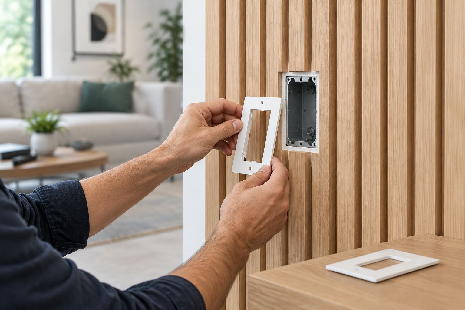
A neat opening is only part of the result. The enclosure arrangement must be correct behind it, and the faceplate must remain removable after the surrounding finish is complete.
Electrical installation and panel fitting
Electrical verification comes before decorative finishing. A switch that pairs successfully with an app can still have an unsuitable load, inadequate enclosure space, or an incorrect mounting arrangement.
- Isolate the circuit. Have the electrician switch off the appropriate breaker, prevent unintended re-energization, and verify absence of voltage with suitable test equipment before handling conductors. A wall switch in the off position does not establish that the box is de-energized.
- Complete the approved wiring arrangement. The electrician should follow the device diagram, connector instructions, grounding requirements, and applicable code. Never use the equipment-grounding conductor as a substitute for a neutral.
- Inspect before closing the box. Confirm secure terminations, proper conductor placement, adequate enclosure capacity, and the correct box extension. Keep wiring inside the enclosure rather than between the panel and wall.
- Test basic operation safely. With the device properly mounted and covered, have the electrician restore power and verify physical switching and supported dimming. Resolve flickering, failure to turn off, or abnormal operation before fitting the panels.
- Fit the decorative finish. Isolate the circuit again before work near the box. Cut panels away from installed wiring, keep adhesive out of the enclosure, and protect cables from panel fasteners.
- Recheck the completed assembly. Confirm that the faceplate sits securely, the switch operates freely, and the plate can be removed independently of the wall panels.
Expected result: The switch works physically, the electrical installation remains enclosed and accessible, and the decorative finish does not interfere with operation or maintenance.
For a 2026 wall-panel project, mark known cable routes before selecting fastening locations. Do not drive screws around a switch box based only on where a cable seems likely to run.
Connected-control setup
Configure remote operation only after physical switching passes its checks. The electrical installation must work as intended before an automation is allowed to control it.
- Follow the device's pairing instructions. Use the manufacturer's current app and manual. Follow the exact on-screen labels shown for your model; there is no universal pairing button or reset sequence.
- Name the switch by room and function. A name such as Bedroom Accent Light is clearer than a default device identifier. Use a name that distinguishes the switched light from other lights in the same room.
- Test commands at the installed location. Verify an on command and an off command. For a supported dimmer, test its approved dimming range and any manufacturer-provided minimum-level adjustment.
- Check physical control afterward. Operate the wall switch again after pairing. Confirm that remote commands do not prevent ordinary use by someone without the app.
- Create one simple routine first. Start with a supported schedule or scene, then verify its behavior before adding more conditions. Check what happens after a power interruption using the manufacturer's documented settings.
Expected result: Physical and remote controls behave consistently, and the first routine performs the intended action without competing commands.
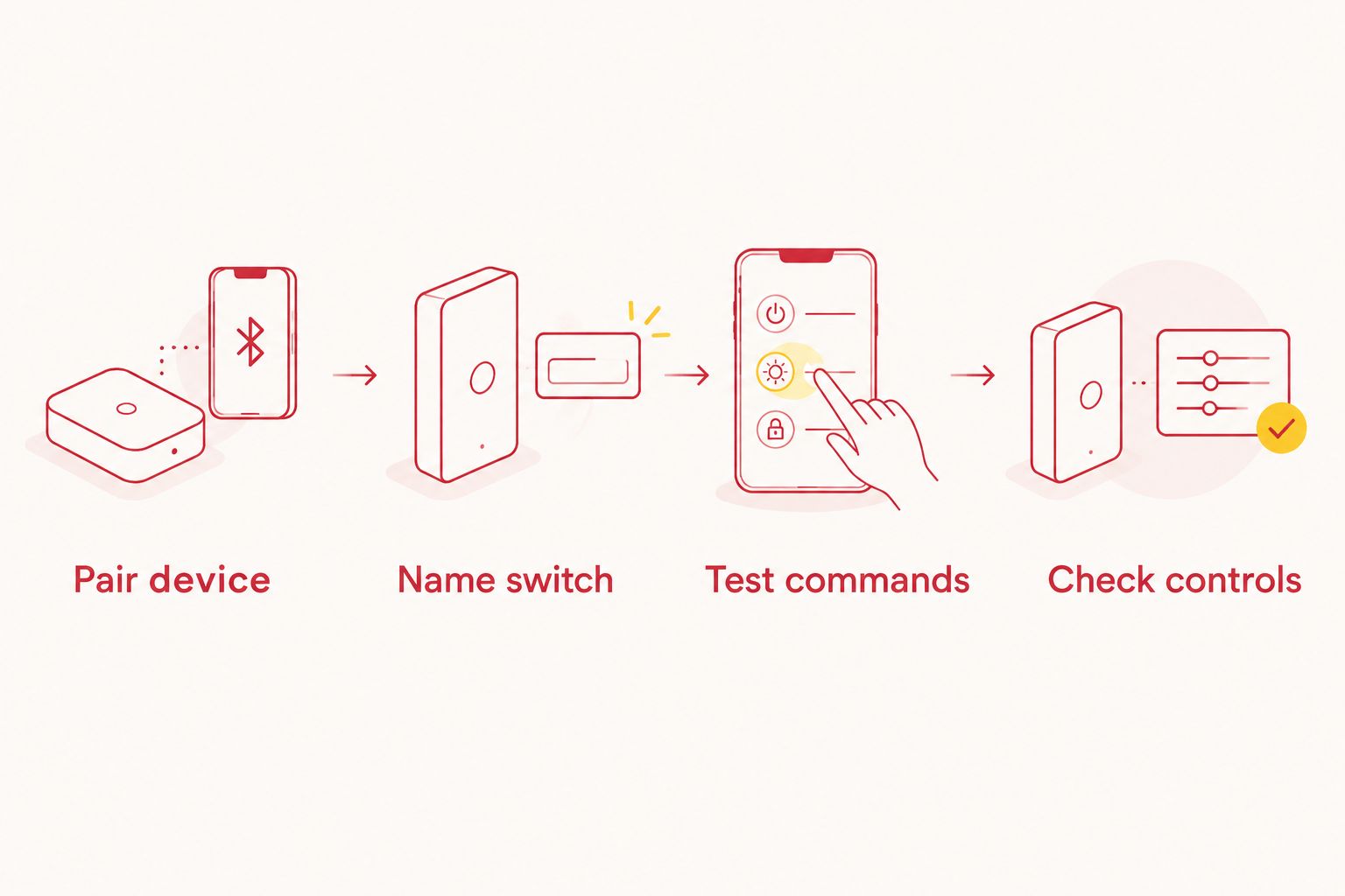
Keep your 2026 setup simple until the completed wall is in place. Test connectivity again after installation rather than treating an earlier pairing test as the final check.
Second workflow: multi-location control
If you control the same light from different positions, use the smart-switch manufacturer's approved multi-location arrangement. Do not assume an existing conventional switch can remain connected unchanged.
| Workflow | Best for | Advantage | Limitation |
|---|---|---|---|
| Single-location smart control | A light controlled from one wall position | One physical control location to configure | Does not add another physical control point by itself |
| Approved multi-location smart control | A light controlled from several wall positions | Preserves convenient control around the room | Requires the exact wiring and companion arrangement supported by the manufacturer |
Have the electrician identify the circuit and confirm which device belongs at each location. Check every affected box for neutral requirements, capacity, and panel build-out—not only the box receiving the main smart device.
After installation, test each physical control separately, then test remote operation. Finish the paneling only after every location works. The Panel Hub wall panels are the decorative finish; they do not determine which multi-location electrical arrangement is supported.
Troubleshooting
The faceplate rocks or leaves an uneven gap
Check whether raised slats or a textured surface prevent flat seating. Plan a flat surround and have the electrician verify the device mounting and box extension. Tightening the plate harder is not the fix for an uneven wall.
The switch cannot pair after panel installation
Confirm the device's required network or hub, then check connectivity at the finished wall. Follow its documented recovery procedure. Do not open an energized box to troubleshoot wireless reception.
The LED light flickers or does not turn fully off
Have the electrician check load compatibility and wiring against the switch instructions. For a compatible dimmer, use only the manufacturer's documented adjustment process. Do not add an unspecified component behind the panels to mask the problem.
One multi-location control stops working
Recheck the approved companion arrangement and circuit identification. Similar-looking controls do not establish compatibility. Isolate the circuit and return the wiring diagnosis to the electrician.
The switch smells hot, discolors, buzzes abnormally, or trips the breaker
Stop using the circuit and have it inspected. If safe, turn off the affected breaker; smoke or fire requires emergency action. Do not dismiss these signs as a normal consequence of fitting wall panels.
Customize your workflow
Once the electrical installation is complete, improve how the room works. Use a supported schedule for predictable lighting, retain clear physical control, and choose panel joints that make the switch surround look intentional.
For a 2026 bedroom update, plan the light, switch, and feature wall together rather than letting the panel pattern dictate electrical access. The wall panels for DIY beginners guide helps you continue the decorative planning without confusing panel fitting with electrical work.
Keep the circuit identification, switch model, and installation instructions with your home records. Photograph the finished box arrangement while the circuit is safely isolated and before the decorative trim conceals its edges.
FAQ
Can I hide a smart switch behind wood wall panels?
Do not bury a conventional wall-mounted smart switch or its electrical box behind permanent paneling. Keep the control usable and the enclosure accessible without damaging the wall finish.
Do smart switches need a neutral wire?
Some smart switches require a neutral, and others use a different approved arrangement. Check the exact model instructions and have an electrician identify the conductors; wire color alone is not sufficient.
Do I need a box extender when adding wall panels?
You need an enclosure arrangement that meets the requirements at the new finished surface. Added wall depth frequently requires an appropriate extension or replacement box, which an electrician should select for the installation.
Can a smart switch work with wood slat panels?
A smart switch can be installed at a wood slat wall when its enclosure, mounting, wiring, and connected load are suitable. Provide a flat faceplate seating area and preserve access to the electrical box.
Can I keep my existing switch at the other end of the room?
Keep it only if the smart-switch manufacturer explicitly supports that multi-location arrangement. Some devices require a specific companion control or different wiring, so have the circuit checked before installation.
Should I pair the smart switch before installing the panels?
Test physical operation and pairing before finishing the decorative wall, then test connectivity again after the panels are installed. Early testing helps separate electrical or setup faults from problems introduced during finishing.
Can acoustic wall panels make electrical wiring safer?
Acoustic performance does not establish electrical safety or suitability as an enclosure. The Panel Hub acoustic wall panels remain decorative materials; compliant boxes, wiring, mounting, and access are separate requirements.
One last thing
A larger faceplate does not correct a recessed electrical box. It can hide the opening while leaving the underlying mounting problem unchanged. Before you admire the finished feature wall, confirm that the enclosure—not just the plate—meets the finished surface correctly.
Related guides
- Grooved wall panels for modern interiors
- Wall panels for bedroom accent walls
- Wall panels for home offices